Digital IO
nVision has support for digital IO. This is helpful to control machinery from image processing applications or to react upon input signals sent from machinery. Digital IO can either use digital IO modules or a PLC (programmable logic controller).
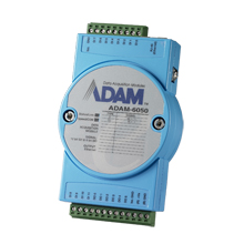
Advantech Adam-60xx Ethernet Modules
nVision supports various digital IO modules from Advantech (http:www.advantech.com).
The modules are connected via LAN or wireless LAN to a PC and support a variety of input/output lines. The modules may have additional features, such as counters, etc. but these are not supported.
module |
bus |
features |
|---|---|---|
ADAM-6050 |
LAN |
12 digital inputs, 6 digital outputs |
ADAM-6050W |
WLAN |
12 digital inputs, 6 digital outputs |
ADAM-6051 |
LAN |
12 digital inputs, 2 digital outputs |
ADAM-6051W |
WLAN |
12 digital inputs, 2 digital outputs |
ADAM-6052 |
LAN |
8 digital inputs, 8 digital outputs |
ADAM-6060 |
LAN |
6 digital inputs, 6 digital outputs |
ADAM-6060W |
WLAN |
6 digital inputs, 6 digital outputs |
ADAM-6066 |
LAN |
6 digital outputs |
The following nodes are available:
node |
purpose |
|---|---|
Adam6000 Module |
An Advantech Adam-6000 module abstraction, which is needed to intialize the module and get information from it. |
Read Inputs |
This is needed to read from digital inputs. |
Write Outputs |
This needed to write to digital outputs. |
The Adam6000 Module node establishes a connection to an Adam device. The IP Address and Port inputs are used to identify the module. The Type input is used to select the connected type of the module. The Module output can be fed into the Read Inputs or Write Outputs nodes.
The Read Inputs node reads the values from the electrical inputs. The DigIn output contains the state of the electrical inputs in the form of a binary integer.
The Write Outputs node writes the value from its DigOut input to its electrical outputs.
The Sync inputs of both the Read Inputs and Write Outputs nodes can be used to establish a defined order.
The Read Inputs node can be polled at regular intervals using the nVision timer.
Beckhoff TwinCAT3
nVision supports direct connection to a Beckhoff PLC. (http:www.beckhoff.de).
You need to install the Beckhoff TwinCAT3 software in order to use the modules from within nVision.
The following nodes are available:
node |
purpose |
|---|---|
Beckhoff PLC |
Establishes the connection to the PLC. |
Read Symbol |
Reads from a symbol in the PLC. |
Write Symbol |
Writes to a symbol in the PLC. |
The Beckhoff PLC node establishes a connection to a PLC over the ADS protocol. It needs an AMS NetId and a Port as input, because this is needed for the unique identification of ADS devices. The output of the Beckhoff PLC node is the PLC itself, which can be fed into the Read Symbol or Write Symbol nodes.
The Read Symbol node reads a symbol from the PLC. The symbol can be choosen from the list at the Symbol input port. This list contains all available symbols in the connected PLC. The Read Symbol node has two outputs. The output port Value gives the value of the accessed symbol. The output port Info gives information about the accessed symbol. These information can be accessed e.g. by the Get Property node.
The Write Symbol node writes a symbol to the PLC at the input port. The symbol can be choosen from the list at the Symbol input port. This list contains all available symbols in the connected PLC. The new value of the symbol can be set on the input port Value.
The Sync inputs of both the Read Symbol and Write Symbol nodes can be used to establish a defined order.
The Read Symbol node can be polled at regular intervals using the nVision timer.
Data Translation OpenLayers
nVision supports various digital IO modules from Data Translation (http:www.datatranslation.com).

The modules are connected via USB or PCI buses to a PC and support a variety of input/output lines. The modules may have additional features, such as counters, etc. but these are not supported.
module |
bus |
features |
|---|---|---|
DT9817 |
USB |
28 digital inputs/outputs |
DT9817-H |
USB |
28 digital inputs/outputs |
DT9817-R |
USB |
8 digital inputs, 8 digital outputs |
DT9835 |
USB |
64 digital inputs/outputs |
DT335 |
PCI |
32 digital inputs/outputs |
DT351 |
PCI |
8 digital inputs, 8 digital outputs |
DT340 |
PCI |
32 digital inputs, 8 digital outputs |
You need to install the Data Translation OpenLayers software in order to use the modules from within nVision. We have used OpenLayers 7.5 to implement the support, so OpenLayers 7.5 or higher is needed.
The following nodes are available:
node |
purpose |
|---|---|
OpenLayers System |
Provide information about the installed DT OpenLayers software and the connected devices. |
OpenLayers Device |
A DT OpenLayers module abstraction, which is needed to intialize the module and get information from it. |
Read Inputs |
This is needed to read from digital inputs. |
Write Outputs |
This needed to write to digital outputs. |
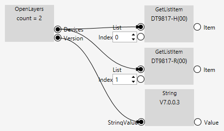
The OpenLayers System node enumerates the OpenLayers devices connected to the PC. The Modules output delivers a list of conected devices. The Version output displays the version of the installed OpenLayers software.
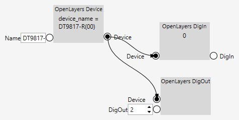
The OpenLayers Module node establishes a connection to an OpenLayers device. The Name input is needed to identify the module. You can find out the name by inspecting the output of the OpenLayers System node. The Module output can be fed into the Read Inputs or Write Outputs nodes.
The Read Inputs node reads the values from the electrical inputs. The DigIn output contains the state of the electrical inputs in the form of an integer.
The Write Outputs node writes the value from its DigOut input to its electrical outputs.
The Sync inputs of both the Read Inputs and Write Outputs nodes can be used to establish a defined order.
The Read Inputs node can be polled at regular intervals using the nVision timer.
Here is an example of how to find out which DT OpenLayers devices are connected.
If you know the name of a DT OpenLayers device, you can also type it directly to initialize the module. The value that you want to output on the digital output is typically not typed in, but calculated somewhere else. Also, the value that is input via the digital inputs is typically used somewhere else in the pipeline.
Imago VisionBox AGE-X
nVision supports the VisionBox AGE-X industrial PCs from Imago Technologies.
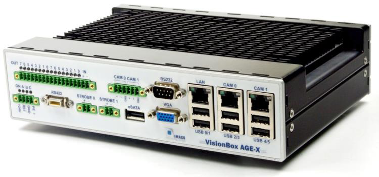

The VisionBox AGE-X is developed for machine vision and has special features for it. But inside it works like a normal PC. The VisionBox AGE-X can boot from a USB 2.0 or eSATA device. The idea is to work with an external hard disk with a normal operation system and an IDE. Boot the system from it and develop directly on the AGE-X. Impuls nVision can be installed on the VisionBox AGE-X. Tip: The Microsoft Windows remote desktop (RDP) is very powerful. Using it you can develop from your normal desktop.
Installation
VisionBox AGE-X device driver
After booting Windows the first time the OS asks for some driver. The delivery package contains all drivers you need. Other drivers can (must if you need this functionality) be installed manually. Select the desired installer and follow the instructions. One of these drivers is for the AGE-X functionality.

Imago SDK
To use the VisionBox AGE-X within nVision, the Imago SDK needs to be installed. The installer includes the SDK. Run the installer for your system: AGE-X Setup 32bit.exe or AGE-X Setup 64bit.exe. Select the desired installer and follow the instructions.
nVision pipelines that make use of the Imago nodes can run on a VisionBox AGE-X only. They can be loaded on a different PC (if the Imago SDK is installed on this PC), but they obviously cannot run on non-VisionBox hardware.
Build an Impuls nVision project
Start nVision, load an image, open a pipeline and you will find the AGE-X nodes in the menu.

The next pages give an overview of the AGE-X functionality and the best way to use it within nVision. This is only an introduction of the general use. The Imago SDK contains a VIB_NET.chm reference for the whole functionality and function description.
Step 1 - Opening the system
On the first step we create the main factory. Before we start let’s have a look to the structure of the framework:
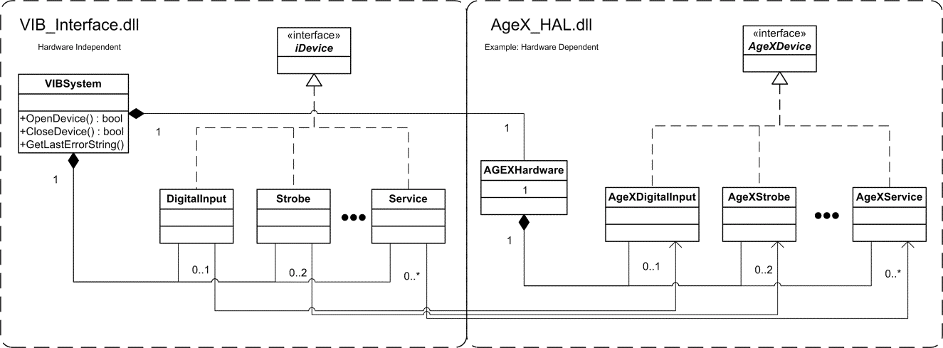
This shows a simplified class diagram of the underlying framework. VIB_NET is a platform independent API to access the hardware functionality. VIBSystem is a factory which creates all devices. One device class groups functions around a physical interface / unit, for example digital inputs or strobe unit. If the box has two independent channels, you can create two instances of each type. For example the AGE-X has two strobe channels. Finally the VIBSystem contains / handles a hardware dependent factory to build a concrete device implementation. It allows one program to run on different Imago PC based boxes that will be created in the future without changes or rebuilds.
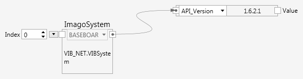
In order to read the version string from the ImagoSystem node, use the GetProperty node (Ctrl-P) and connect the ImagoSystem node output to it.
Since opening the system usually is a one-time step, it can be done globally; either in the system globals of nVision or in the global settings of the pipeline.
Step 2 - Using simple devices
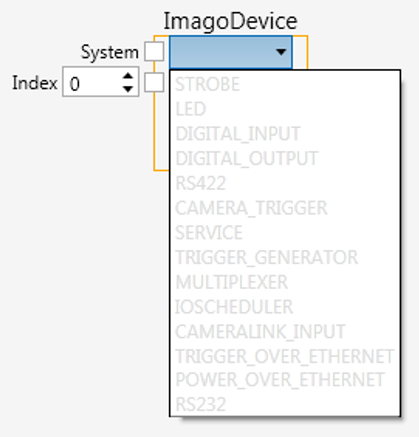
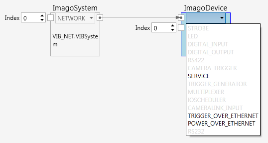
An ImagoDevice node, which is not connected to an ImagoSystem node shows all possible devices, but they are all greyed out.
Once an ImagoDevice node is connected to the ImagoSystem node, the available devices are displayed prominently and can be easily selected.
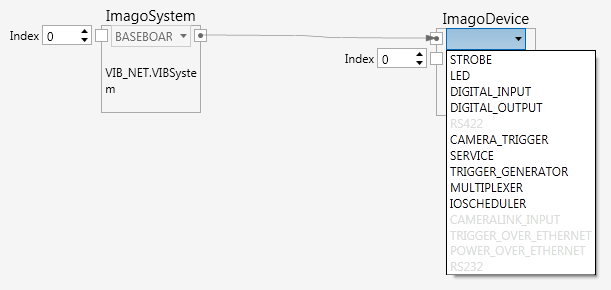
The devices of a Baseboard system are different than those of a Network system.
Since opening the devices usually is a one-time step, it can be done globally; either in the system globals of nVision or in the global settings of the pipeline.
Here is an example that shows how to set a digital output. The DIGITAL_OUTPUT Operation node shows a number of methods that can be called on a digital output.
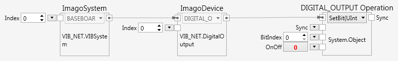
The example shows how to set a single bit on a digital output.
Step 3 - Using a complex device
A more complex device is the strobe out. This example cannot explain the strobe unit in detail. Please refer to the function reference in the Imago SDK documentation. To run the code successfully, please connect a zero Ω bridge at the first output.
Note: Every channel of the strobe unit must be calibrated (by default done by Imago), otherwise the initialization will fail.
To use the strobe, several operations must be executed in a row:
- Initialize the strobe
- Set the trigger mode
- Set the desired current

Setting the trigger mode and current needs to be done after initializing the device. In order to establish this order, the Sync output of Init() is connected to the Sync input of set_TriggerMode(), and the Sync output of set_TriggerMode() is connected to the Sync input of set_Current(). Connecting the Sync ports in this way establishes an order of execution in a graph of operations, where otherwise the order of execution would be undefined.
Good to know
- Every Imago SDK function is thread safe.
- The Imago SDK framework is process safe.
- The device nodes show the available methods of a specific device. They also list property setters in the form of
set_Xxxx(). Property setters can be distinguished from methods, which are listed in the formXxxxxYyyyy(). - Properties of the Imago nodes can be read with the GetProperty node (Ctrl-P).
- Every function in the Imago SDK can be called with the graphical nodes.