CAD Drawing Support
nVision can import CAD drawings and convert them to images. Once the CAD drawing has been converted to an image, the usual image processing methods can be applied. Applications of particular interest are:
- match CAD drawings to acquired images, and then inspect differences.
- use CAD drawings to define regions of interest for part inspection.
nVision supports import of drawings from Autocad DXF files and Trumpf GEO files.
Import DXF files
DXF is a format defined and controlled by Autodesk (http:www.autodesk.com). Used within AutoCad, it has become the de-facto standard for CAD drawing interchange - even between different vendors. While the DXF format is syntactically simple and easy to parse, the semantics are complicated, because the format is not documented very well. Also, it has been changed and extended in a somewhat ad-hoc manner during the many years since the first versions of AutoCad, and this respecting and carrying on this heritage makes it difficult.
For this reason one cannot simply state that DXF drawing import will work in any case. nVision supports a partial 2D subset only. Particularly, the following primites are supported:
primite |
features |
|---|---|
line |
a line segment |
arc |
a circular arc |
circle |
a full circle |
polygon |
a polygon |
Files containing additional primitives usually can be read, but the unknown items are ignored.
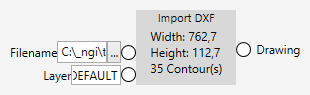
When importing a DXF file, you need to specify the filename and the name of the layer you want to import. If there are multiple layers that you need to import, you can use several import nodes in parallel.
Import GEO files
GEO is the format used by laser cutting machines of TRUMPF (http:www.trumpf.com).
nVision supports a subset of the GEO format related to 2D.
primite |
features |
|---|---|
line |
a line segment |
arc |
a circular arc |
circle |
a full circle |
Files containing additional primitives usually can be read, but the unknown items are ignored.
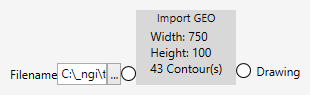
When importing a GEO file, you need to specify the filename.
Render CAD drawings
Both import nodes create a CAD drawing when successful. The drawing has several properties that allow you to find out more information about the drawing, such as the height and width (in mm) as well as the contours contained in it.
Also, the drawing can be rendered into an image.

When rendering a CAD drawing, the resolution parameter tells you how fine the rendering will be. A value of 1 means that one pixel will have a size (area) of 1 mm (1 mm²). A value of 0.1 means that one pixel will have a size (area) of 0.1 mm (0.01 mm²). The actual size of the rendered image is determined by the width and height of the imported drawing (in mm), divided by the resolution parameter. The smaller (finer) the resolution parameter is, the bigger the rendered image will be.
The Fill parameter controls whether the drawing contours will be filled or outlined only.